ALL WORK SHOULD BE CARRIED OUT BY SUITABLY QUALIFIED PERSONNEL TO THE LATEST IEE REGULATIONS AND SITE REGULATIONS.
Immersion Heater Installation, Wiring and Maintenance Instructions
1. Installation.
1.1 When fitting the heater, sufficient clearance should be allowed so that the element is not covered by the sludge or deposits which may settle on the bottom of the tank.
1.2 The thermostat or cutout if fitted and offset in the heater, should be at the top side of the element bundle.
1.3 Ensure that the gasket makes a drip proof seal between the heater and the tank, and that there is sufficient room to withdraw the heater.
1.4 The heater should not be mounted wher it is likely to suffer from shock / vibration, explosive / hazardous atmosphere or corrosive / dust laden environments, unless it has been specifically designed for such applications.
2. Wiring.
2.1 Ensure that the mains supply available corresponds with the supply voltage on the heater nameplate, and that a neutral line is connected when the heater is so designed.
2.2 Ensure that the sizes of supply cables and contactors are adequate for the electrical load they carry.
2.3 If the heater is divided into anumber of stages, then the section of elements adjacent to the safety cut out probe must be wired into the first heater stage, ie, the stage that is continuously switched on whilst the heater is energised.
2.4 Chech that the thermostat / safety cutout, if fitted, is corectly wired to ensure complete shutdown of the heater, ie, in series with the coil of the main contactor. Ensure the rating of the conatactors and the fuses are adequate.
2.5 Check that a sufficently good earth is conneccted to the heater unit.
2.6 check all electrical connections for tightness, including all element terminations.
2.7 check that the terminal cover is correctly fitted before switching the heater on.
3. Operation.
3.1 Check that the active part of the element is well covered by the fluid.
3.2 It is general practice for control to be automatic, a thermostat is used to sense any change in heat requirement and then operate the heater directly (up to 3kW) or through a contactor (over and above 3kW).
3.2 iIn the event of shutdown caused by overheating, the main isolator must be switched off before checking the system. The fluid level should be checked and the control systems inspected. Reset the cutout (if fitted).
4. Maintenance.
4.1 The heater must be isolated before removing the terminal cover, and should not be switched on until the terminal cover has been replaced and the system refilled with fluid.
4.2 Periodically inspect the heater to ensure that there is no build up of deposit on the elements.
ALL WORK SHOULD BE CARRIED OUT BY SUITABLY QUALIFIED PERSONNEL TO THE LATEST IEE REGULATIONS AND SITE REGULATIONS.
Example Wiring.
Wiring specifications have altered over the years, as detailed below –
| Pre-1977 IEE | Pre-2004 IEE | Current IEC | |
|---|---|---|---|
| Protective earth (PE) | Green | Green/yellow bi-colour | Green/yellow bi-colour |
| Neutral (N) | Black | Black | Blue |
| Single phase: Line (L) | Red | Red | Brown |
| Three-phase: L1 | Red | Red | Brown |
| Three-phase: L2 | Yellow | Yellow | Black |
| Three-phase: L3 | Blue | Blue | Grey |
For further detail, here are the IEE Wiring Regulations
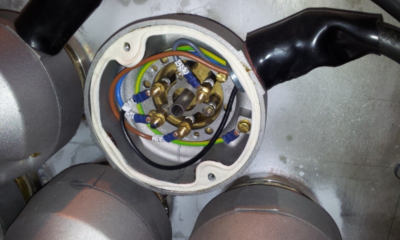
An example of a correctly wired 3-phase heater, kindly supplied by one of our customers –